


- Batteries Products
- Cooling & Thermal Management
- Development Boards & Evaluation Kits
- Lighting Products
- Passive Component
- Relays
- Semiconductors - ICs
- Sensors & Transducers
Jit Sen Electronics Sdn Bhd
52A, 56 & 56-1,
Jalan MP 2,
Taman Merdeka Permai,
75350 Batu Berendam,
Melaka, Malaysia.
+606-337 5257
+6012-677 5183
Mr. Kwong
+6012-623 0939
Mr. Adam - (Technical Support)
+606-333 8726
jitsen5257electronics@gmail.com
+60126775183
+60126775183
LDR Sensor Module (Light Dependent Resistor), LDR-MOD
| Previous | 3 / 12 | Next |
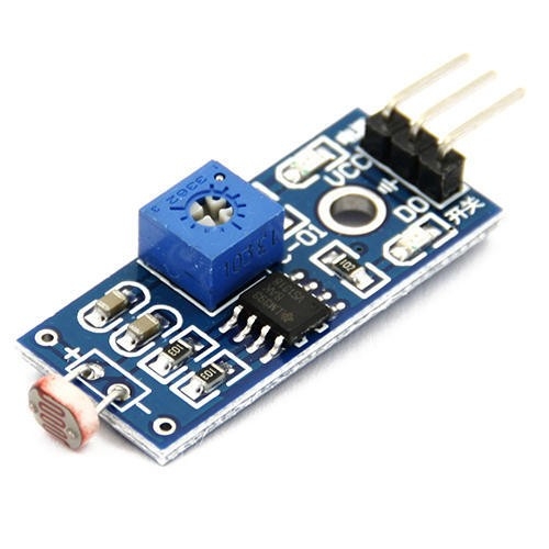
- Able to detect ambient brightness and light intensity
- Adjustable sensitivity (via blue digital potentiometer adjustment)
- Operating voltage 3.3V-5V
- Digital switching outputs (0 and 1) -D0
- With fixed bolt hole for easy installation
- Small board PCB size: 3cm * 1.6cm
- Power indicator (Red) and the digital switch output indicator (Green)
- Features wide range voltage comparator LM393
Pin outs:
- External 3.3V-5V VCC
- External GND ground
- DO digital output interface, a small plate (0 and 1)
How to use:
- Photosensitive resistor module most sensitive to environmental light intensity is generally used to detect the ambient brightness and light intensity.
- Module light conditions or light intensity reach the set threshold, DO port output high, when the external ambient light intensity exceeds a set threshold, the module D0 output low;
- Digital output D0 directly connected to the MCU, and detect high or low TTL, thereby detecting ambient light intensity changes;
- Digital output module DO can directly drive the relay module, which can be composed of a photoelectric switch;
Step 1: Introduction
LDR sensor module is used to detect the intensity of light. It is associated with both analog output pin and digital output pin labelled as AO and DO respectively on the board. When there is light, the resistance of LDR will become low according to the intensity of light. The greater the intensity of light, the lower the resistance of LDR. The sensor has a potentiometer knob that can be adjusted to change the sensitivity of LDR towards light.
Specification:
- Input Voltage: DC 3.3V to 5V
- Output: Analog and Digital
- Sensitivity adjustable
Step 2: Pin Definition


Step 3: Sample Hardware Installation (Analog Output)

Step 4: Sample Source Code
void setup()
{
Serial.begin(9600);
}
void loop()
{
unsigned int AnalogValue;
AnalogValue = analogRead(A0);
Serial.println(AnalogValue);
}
You can also download the sample source code attached on top and upload it into Arduino. After that open "Serial Monitor" to see the result.