

- Batteries Products
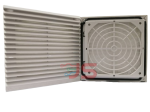
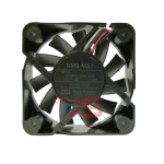
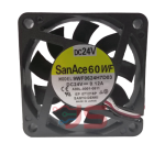
- Cooling & Thermal Management
- Development Boards & Evaluation Kits
- Lighting Products
- Passive Component
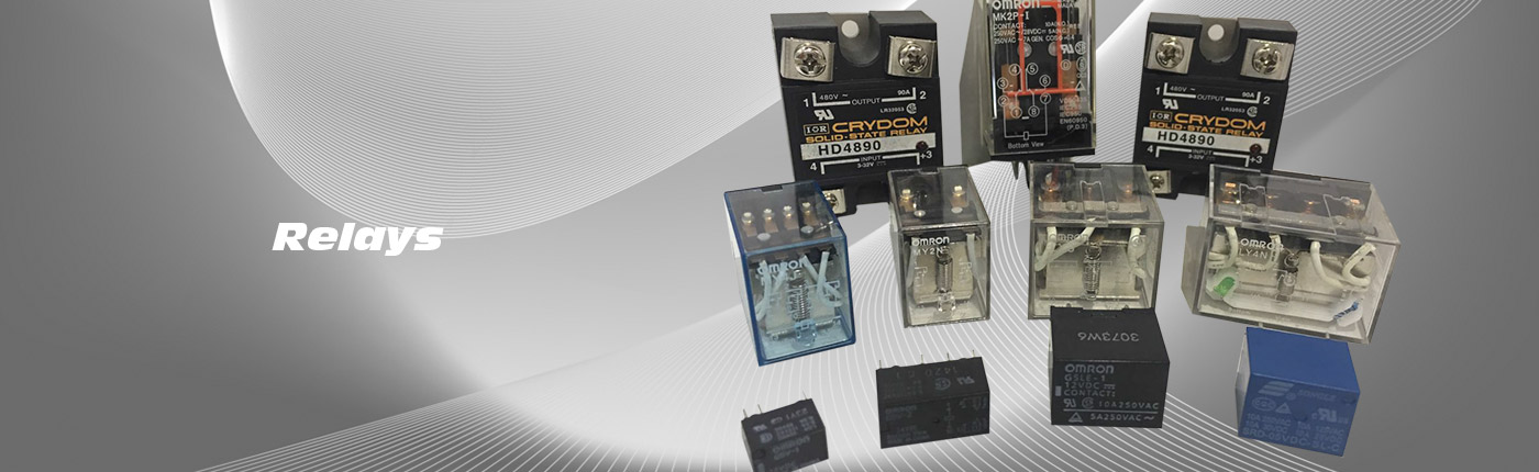
- Relays
- Semiconductors - ICs
- Sensors & Transducers
Jit Sen Electronics Sdn Bhd
52A, 56 & 56-1,
Jalan MP 2,
Taman Merdeka Permai,
75350 Batu Berendam,
Melaka, Malaysia.
+606-337 5257
+6012-677 5183
Mr. Kwong
+6012-623 0939
Mr. Adam - (Technical Support)
+606-333 8726
jitsen5257electronics@gmail.com
+60126775183
+60126775183
Camera Module OV7670 CMOS VGA Res. 640x480 SCCB Interface Compatible w/ I2C Interface
| Previous | 7 / 12 | Next |

OV7670 image sensor,small size,low voltage,providing single-chip VGA camera and image processor for all functions. By SCCB bus control ,you can output the entire frame , sub-sampled , taking a variety of windows , etc. Resolution 8 affect the data .The product is VGA images up to 30 frames / sec.
Features
- Mounted with high quality F1.8 / 6mm lens
- High sensitivity for low-light operation
- Low operating voltage for embedded application
- Standard SCCB interface compatible with I2C interface
- 8bit Output Format (YUV/ YCbCr 4:2:2/RGB565-555-444/RAW RGB Data)
- Serial Camera Control Bus (SCCB)
- Support VGA, CIF and from CIF to 40 x 30 format
- Vario Pixel method for sub-sampling
- Auto Image Control: AEC, AGC, AWB, ABF, ABLC
- Image Quality Control: Color saturation, hue, gamma, sharpness and anti-blooming
- ISP includes noise reduction and defect correction
- Support image scaling
- Lens shading correction
- Flicker 50/60Hz auto detection
- Color saturation level auto adjust
- Edge enhancement level auto adjust
- De-noise level auto adjust
Specifications
- Resolution 640×480 VGA
- Optical size: 1/6 inch
- Vision Angle: 25 degree.
- Max. Frame Rate: 30fps VGA.
- Sensitivity: 1.3V / (Lux-sec).
- Working Voltage: DC 3.3V with onboard regulator
- Operating Power: 60mW/15fps
- Sleeping Mode: <20μA.
- Operating Temperature: -30 to 70 deg C.
- Output Format: YUV/YCbCr4:2:2 RGB565/555/444 GRB4:2:2 Raw RGB Data (8 digit)
- Signal to Noise Ratio: 46 dB
- DynamicRange: 52 dB
- Browse Mode: By row
- Electronic Exposure: 1 to 510 row
- Pixel Coverage: 3.6μm x 3.6μm
- Duck Current: 12 mV/s at 60 °c
- PCB Size (L x W): 3.5 x 3.5 cm
Step 1: General Description
This camera module can perform image processing such as AWB (auto white balance), AE (automatic exposure) and AGC (automatic gain control), for the video signal coming from CMOS sensor. What’s more, in fusion of other advanced technology such as image enhancement processing under low illumination, and image noise intelligent forecast and suppress, this module would output high quality digital video signals by standard CCIR656 interface. OV7670 built-in JPEG decoder supported reatime encoding for collected image, and external controller can easily read the M – JPEG video streams, achieving the camera design of double stream. OV7670 supported motion detection and OSD display function of screen characters and pattern overlay, capable of self-defining detection area and sensitivity.
Step 2: Test OV7670 Camera Module - Needed Tool for Testing
-
Hardware
SD Module
Digital key module
Jumper wire
USB cable
-
Software
Camera_VC0706_TEST
Arduino IDE(download it from official website)
Step 3: Hardware Connection


- Connect the hardware as the diagram shows.
- Physical diagram.
Step 4: Software Use and Code Programming


- Firstly download the two files of Camera_OV0706_lib and Camera_OV0706_TEST from the Camera Module Code written by ElecFreaks and then unzip it.
-
Put the unzipped file of Camera_OV0706_lib into the Arduino IDE folder of Libraries.
-
Open unzipped file of Camera_OV0706_TEST, and the program the code into UNO. The detailed steps are demonstrated in the pictures.
-
Click Tools,and then choose the board of Arduino UNO.
-
Click Tools / Serial Port,and then choose the corresponding COM number.
-
And then click the button of programming like below in red rectangle, program the code into the UNO board until done uploading appears.
-
Finally open the monitoring serial port as below in red rectangle.
-
When the serial port display the data like demonstrated below, you can press the digital keys to take a photo.
-
If photo was taken successfully, the serial port would be displayed.
Until now, the module testing has been completed. Thanks for reading.