


- Batteries Products
- Cooling & Thermal Management
- Development Boards & Evaluation Kits
- Lighting Products
- Passive Component
- Relays
- Semiconductors - ICs
- Sensors & Transducers
Jit Sen Electronics Sdn Bhd
52A, 56 & 56-1,
Jalan MP 2,
Taman Merdeka Permai,
75350 Batu Berendam,
Melaka, Malaysia.
+606-337 5257
+6012-677 5183
Mr. Kwong
+6012-623 0939
Mr. Adam - (Technical Support)
+606-333 8726
jitsen5257electronics@gmail.com
+60126775183
+60126775183
Color Recognition Sensor Module TCS3200
| Previous | 8 / 12 | Next |

The TCS230 is a color light-to-frequency converter on single CMOS integrated circuit. The output is a square wave(50% duty cycle) with frequency directly proportional to light intensity (irradiance). The full-scale output frequency can be scaled by one of three preset values via two control input pins. Output enable (OE) places the output in the high-impedance state for multiple-unit sharing of a microcontroller input.
Library example code includes:
- Simple blocking read from the sensor
- Simple RGB non-blocking read
- Example incorporating sensor calibration
- Color learning and matching

Features:
- The TCS3200 is TCS230 upgraded version better
- Power supply DC 3v - 5v
- Resistance to light interference
- White LED can be controlled on, off.
- Can detect non-luminous object color
- Best detection distance 1cm
- Chip pins all has drawn for standard 100. Put the needle (2.54 mm).
- Mil-convenient for bitmap board.
- Programmable color and full-scale output frequency.
- Communicate directly with a microcontroller.
- Low-profile surface mount package.
Item size: 31*23*10mm
Net weight: 5g
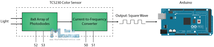
How TCS230 Color Sensor Works
The TCS230 senses color light with the help of an 8 x 8 array of photodiodes. Then using a Current-to-Frequency Converter the readings from the photodiodes are converted into a square wave with a frequency directly proportional to the light intensity. Finally, using the Arduino Board we can read the square wave output and get the results for the color.
If we take a closer look at the sensor we can see how it detects various colors. The photodiodes have three different color filters. Sixteen of them have red filters, another 16 have green filters, another 16 have blue filters and the other 16 photodiodes are clear with no filters.
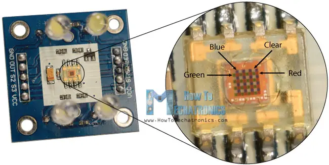
Each 16 photodiodes are connected in parallel, so using the two control pins S2 and S3 we can select which of them will be read. So for example, if we want to detect red color, we can just use the 16 red filtered photodiodes by setting the two pins to low logic level according to the table.
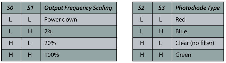
The sensor has two more control pins, S0 and S1 which are used for scaling the output frequency. The frequency can be scaled to three different preset values of 100 %, 20 % or 2%. This frequency-scaling function allows the output of the sensor to be optimized for various frequency counters or microcontrollers.
You can get the components needed for this Arduino tutorial from the links below:
- TCS230 TCS3200 Color Sensor…… Amazon / Aliexpress
- Arduino Board ………………………….. Amazon / Aliexpress
*Please note: These are affiliate links. I may make a commission if you buy the components through these links.
I would appreciate your support in this way!
TCS230 Color Sensor Source Code
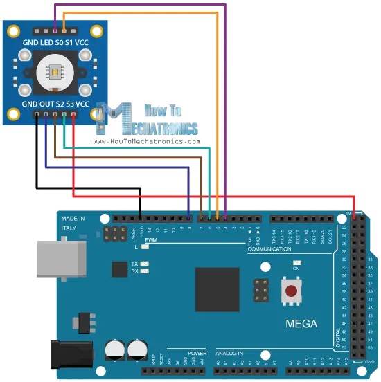
Description: First we need to define the pins to which the sensor is connected and define a variable for reading the frequency. In the setup section we need to define the four control pins as outputs and the sensor output as an Arduino input. Here we also need to set the frequency-scaling, for this example I will set it to 20%, and start the serial communication for displaying the results in the Serial Monitor.
In the loop section, we will start with reading the red filtered photodiodes. For that purpose we will set the two control pins S2 and S3 to low logic level. Then using the “pulseIn()” function we will read the output frequency and put it into the variable “frequency”. Using the Serial.print() function we will print the result on the serial monitor. The same procedure goes for the two other colors, we just need to adjust the control pins for the appropriate color.
- /* Arduino Color Sensing Tutorial
- *
- * by Dejan Nedelkovski, www.HowToMechatronics.com
- *
- */
- #define S0 4
- #define S1 5
- #define S2 6
- #define S3 7
- #define sensorOut 8
- int frequency = 0;
- void setup() {
- pinMode(S0, OUTPUT);
- pinMode(S1, OUTPUT);
- pinMode(S2, OUTPUT);
- pinMode(S3, OUTPUT);
- pinMode(sensorOut, INPUT);
- // Setting frequency-scaling to 20%
- digitalWrite(S0,HIGH);
- digitalWrite(S1,LOW);
- Serial.begin(9600);
- }
- void loop() {
- // Setting red filtered photodiodes to be read
- digitalWrite(S2,LOW);
- digitalWrite(S3,LOW);
- // Reading the output frequency
- frequency = pulseIn(sensorOut, LOW);
- // Printing the value on the serial monitor
- Serial.print("R= ");//printing name
- Serial.print(frequency);//printing RED color frequency
- Serial.print(" ");
- delay(100);
- // Setting Green filtered photodiodes to be read
- digitalWrite(S2,HIGH);
- digitalWrite(S3,HIGH);
- // Reading the output frequency
- frequency = pulseIn(sensorOut, LOW);
- // Printing the value on the serial monitor
- Serial.print("G= ");//printing name
- Serial.print(frequency);//printing RED color frequency
- Serial.print(" ");
- delay(100);
- // Setting Blue filtered photodiodes to be read
- digitalWrite(S2,LOW);
- digitalWrite(S3,HIGH);
- // Reading the output frequency
- frequency = pulseIn(sensorOut, LOW);
- // Printing the value on the serial monitor
- Serial.print("B= ");//printing name
- Serial.print(frequency);//printing RED color frequency
- Serial.println(" ");
- delay(100);
- }
Now if we run the Serial Monitor we will start getting some values. These values depend on the selected frequency-scaling, as well as from the surrounding lighting.
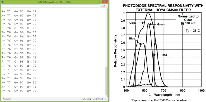
Note here that three values differ due to the different sensitivity of each photodiode type, as seen from the photodiode spectral responsivity diagram from the datasheet of the sensor.
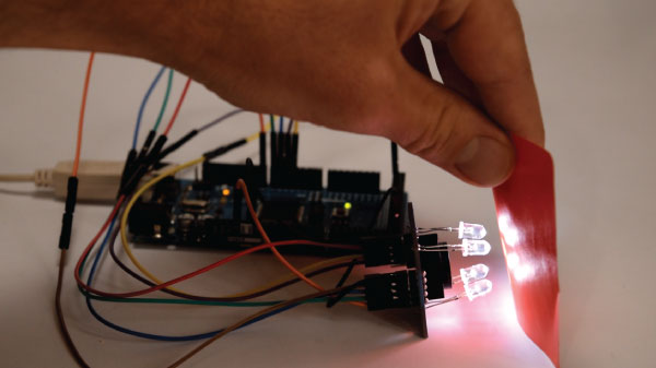
Nevertheless, now let’s see how the values react when we will bring different colors in front of the sensor. So for example, if we bring red color, the initial value will drop down, in my case from around 70 to around 25.
So now if we want to represent the detected colors with the RGB Model which has values from 0 to 255, we will use the map() function to map or convert the readings to the values from 0 to 255.
- //Remaping the value of the frequency to the RGB Model of 0 to 255
- frequency = map(frequency, 25,70,255,0);
The value of 70 will be mapped to 0, and the value of 25 to 255. The same procedure goes for the two other colors.
- /* Arduino Color Sensing Tutorial
- *
- * by Dejan Nedelkovski, www.HowToMechatronics.com
- *
- */
- #define S0 4
- #define S1 5
- #define S2 6
- #define S3 7
- #define sensorOut 8
- int frequency = 0;
- void setup() {
- pinMode(S0, OUTPUT);
- pinMode(S1, OUTPUT);
- pinMode(S2, OUTPUT);
- pinMode(S3, OUTPUT);
- pinMode(sensorOut, INPUT);
- // Setting frequency-scaling to 20%
- digitalWrite(S0,HIGH);
- digitalWrite(S1,LOW);
- Serial.begin(9600);
- }
- void loop() {
- // Setting red filtered photodiodes to be read
- digitalWrite(S2,LOW);
- digitalWrite(S3,LOW);
- // Reading the output frequency
- frequency = pulseIn(sensorOut, LOW);
- //Remaping the value of the frequency to the RGB Model of 0 to 255
- frequency = map(frequency, 25,72,255,0);
- // Printing the value on the serial monitor
- Serial.print("R= ");//printing name
- Serial.print(frequency);//printing RED color frequency
- Serial.print(" ");
- delay(100);
- // Setting Green filtered photodiodes to be read
- digitalWrite(S2,HIGH);
- digitalWrite(S3,HIGH);
- // Reading the output frequency
- frequency = pulseIn(sensorOut, LOW);
- //Remaping the value of the frequency to the RGB Model of 0 to 255
- frequency = map(frequency, 30,90,255,0);
- // Printing the value on the serial monitor
- Serial.print("G= ");//printing name
- Serial.print(frequency);//printing RED color frequency
- Serial.print(" ");
- delay(100);
- // Setting Blue filtered photodiodes to be read
- digitalWrite(S2,LOW);
- digitalWrite(S3,HIGH);
- // Reading the output frequency
- frequency = pulseIn(sensorOut, LOW);
- //Remaping the value of the frequency to the RGB Model of 0 to 255
- frequency = map(frequency, 25,70,255,0);
- // Printing the value on the serial monitor
- Serial.print("B= ");//printing name
- Serial.print(frequency);//printing RED color frequency
- Serial.println(" ");
- delay(100);
- }
Note that the colors aren’t that much accurate but they are still good enough for simple projects. As another example of the TCS230 color sensor in my next video we will learn how to make an Arduino Automatic Color Sorting Machine.