


- Batteries Products
- Cooling & Thermal Management
- Development Boards & Evaluation Kits
- Lighting Products
- Passive Component
- Relays
- Semiconductors - ICs
- Sensors & Transducers
Jit Sen Electronics Sdn Bhd
52A, 56 & 56-1,
Jalan MP 2,
Taman Merdeka Permai,
75350 Batu Berendam,
Melaka, Malaysia.
+606-337 5257
+6012-677 5183
Mr. Kwong
+6012-623 0939
Mr. Adam - (Technical Support)
+606-333 8726
jitsen5257electronics@gmail.com
+60126775183
+60126775183
PIR Motion Sensor Module HC-SR501 w/ Adjustable Delay Time & Output Signal
| Previous | 12 / 12 | Next |
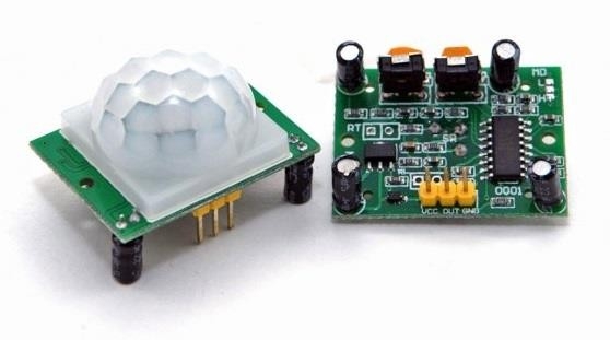
Both revisions of this sensor use the same Fresnel lens, and basic functionality remains the same between the two (for example you can use the same test programs). However, there were a number of improvements and updates made to Revision B, and if using Revision A in your project the following information should be noted and used.
Key Features
- Detection range up to 20 feet
- Single bit output
- Jumper selection single or continuous trigger output mode
- 3-pin SIP header ready for breadboard or through-hole project
Specifications
- Operating voltage: DC 5 - 12V
- Static power consumption: 65 mA
- Output Signal: 3V TTL
- Detection Distance: Up to 6 meter (Adjustable)
- Sensing Range: Less than 120° degree angle, 6 meters
- Delay Time: 5 - 200s (Adjustable)
- Adjustable Trigger: L: non repeatable trigger - H: repeatable trigger
- Operating Temperature: -15 to +70°C
- Dimensions: 32 x 24mm, screw hole distance 28mm
* Note: Driving an external load requires a transistor or MOSFET.
Step 1: Provide Power to the Module


With the power supply OFF
Connect one lead from positive on the power supply to the VCC pin on the module (from the 5v pin on Arduino if you're using that for power)
Connect one lead from negative on the power supply to the GND (ground) pin on the module (GND pin on Arduino if that's your power source)
And that's it, turn on the power and you'll have a working PIR Motion Detector. Just one problem, you'll never know when it detects motion. You might want to move on to step two where we'll add the LED so you know when stuffs moving around that module.
Step 2: Adding the LED


The center pin on the module is labeled "OUT". And that's what it does, it sends current out that pin when the module detects motion. We are going to use that current (approx 3.3v) to light up our LED.
Connect the OUT pin of the module to the positive lead on the LED (the positive lead on the LED will be the longer of the two, you can also figure out the positive lead by looking inside the LED where you will see two contact plates - the smaller of which is positive)
Connect the LEDs negative lead to your power supplies GND
Now that's really it. Turn on the power and the LED should light up when the module detects motion.
Please note that the LED will turn off after the module no longer detects motion. If you wave your hand over the module as soon as the LED turns off, nothing will happen. The LED won't turn on nor will the module wave back at you. There is a built in delay in the module before it will detect motion again, the default on mine is 5 seconds.
Step 3: Using Arduino Board As Power Source


If you are NOT currently using your Arduino board as the power supply then follow the steps below. If you are already using the board to supply power hang in there a second while we get everyone doing that, or just go to Step 4.
To supply power from your board;
REMOVE any power source currently connected to the breadboard, do the same for your Arduino board and then;
1. Connect the 5v pin on the board to positive on the breadboard
2. Connect the GND pin on the board to negative on the breadboard
For those of you that just switched to your Arduino board for the power source, double check things still work. Apply power to your Arduino board, it should now be supplying power to the PIR module and the LED should turn on when motion is detected. It should not matter, at this point, what code is running on your Arduino because all we are doing is using it for a power source.
That's working, great! Let's move on then...
Step 4: Wiring Changes for Using the Arduino Board


Ok, we are getting close. Here are the wiring changes we need to make.
1. Move the module's OUT wire from the positive lead on the LED To pin 2 on your Arduino board.
2. Connect pin 13 on your Arduino board to the positive lead on the LED (where you just moved the wire above from)
Well that's that! Your Arduino board is now supplying the power for this little adventure, it will also receive "input" from the module on pin 2, and send power to the LED via pin 13 when the code tells the board to do so.
Well now, isn't this special! All we have left is uploading the code to your Arduino board and that little sucker will be in charge of the LED. And the code you need is in step 5.
Step 5: Code for Your Arduino Board
Here's a very stripped down version of code that will accomplish our goal of using your Arduino board with a PIR Motion Detector module. Ok, big leap here but I'm assuming you know how to copy and paste between programs. But here's a hint, highlight and copy the code below first, open your Arduino program, open a new file and select Edit, then click Select All, select Edit again, then click Paste. Save that file and upload it to your board.
If you get any compile errors make sure all the default code you see when you open a new file is deleted. Also make sure that all of the code below was copied and appears the same in the program as it does below (well, except for the word-wrap I see on my own notebook, download the PDF - the code looks better).
11/2/15 Update: I attached the code file. Right click the file, select SAVE AS and save it to a location where you'll be able to find it again. :-) It will also want to create a folder with the same name as the file when you save it - let it do so. Then just double click the saved file and (if your file associations are correct) the Arduino program will open with the code ready to go for you.
------------------------- COPY EVERYTHING BELOW THIS LINE ----------------------------------
//PIR Motion Detection Module demonstration code - not intended for practical use
int LED = 13; // The word "LED" can know be used throughout the program and will always reference pin 13
int Sensor = 2; // The word "Sensor" can know be used throughout the program and will always reference pin 2
int val = LOW; // "val" will be a variable used to store the state (HIGH or LOW) of the sensor
void setup()
{
pinMode(LED, OUTPUT); // We just told the program that LED (pin 13) will be used for output
pinMode(Sensor, INPUT); // And this tells the program that Sensor (pin 2) will be used for input
}
void loop()
{
val = digitalRead(Sensor); // To determine if "val" is HIGH or LOW this checks the state of the Sensor (pin 2)
if (val == HIGH)digitalWrite(LED, HIGH); // turn on the LED by applying voltage to pin 13
if (val == LOW)digitalWrite(LED, LOW); // turn off the LED by shutting off voltage to pin 13
}
----------------------- COPY EVERYTHING ABOVE THIS LINE -----------------------------
Now we're really done!! Have fun and don't stay up all night waving your hand in front of the PIR motion detector because you like watching the LED turn on and off.